Classic Mini Disk Brake Assembly

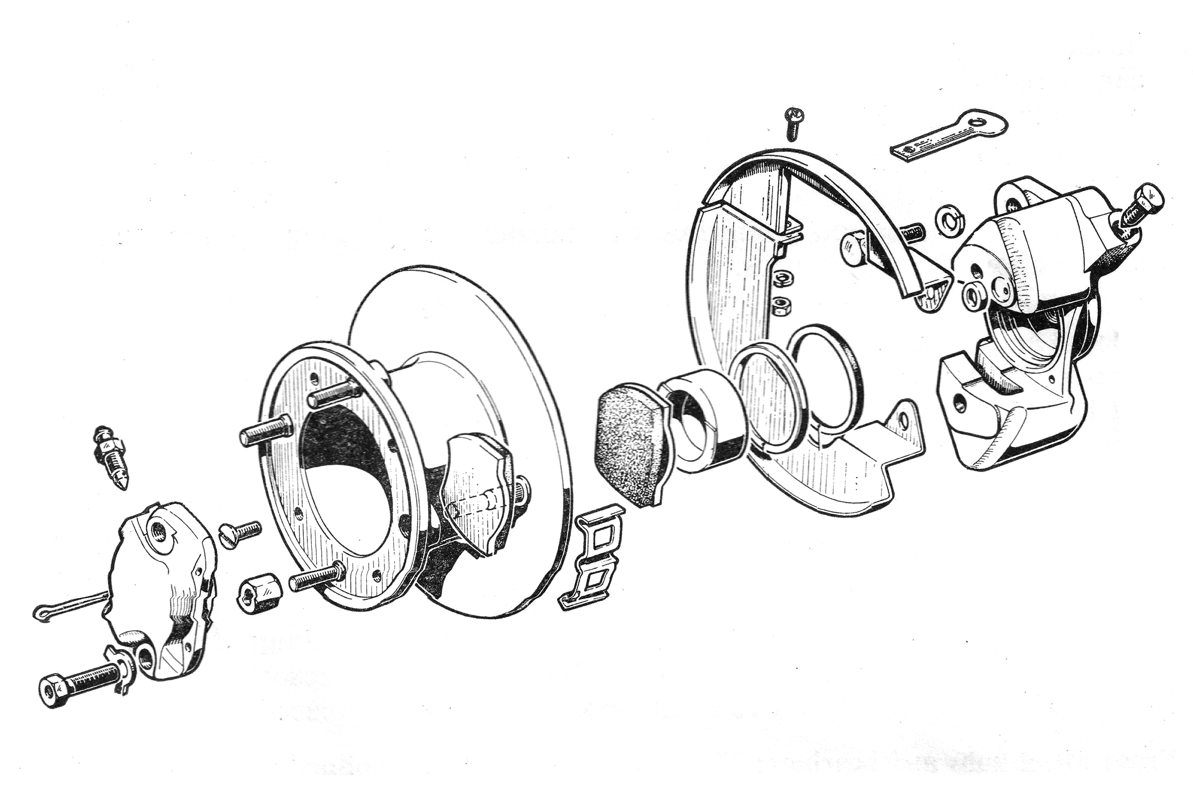
A diagram showing the Classic Mini disk brake assembly.

On Mini models with a single leading brake shoe arrangement one square headed adjuster is found on each backplate
On Eli' and Hornet models with twin leading shoe on the front wheels, two adjusters 'A' and 'B' are provided. To tighten the brakes turn the adjusters clockwise 'C'
On Eli’ and Hornet models with twin leading shoe on the front wheels, two adjusters ‘A’ and ‘B’ are provided. To tighten the brakes turn the adjusters clockwise ‘C’
Never try to undo the flexible hose before unscrewing the union nut  (1) followed by the attachment nut (2)
Never try to undo the flexible hose before unscrewing the union nut (1) followed by the attachment nut (2)

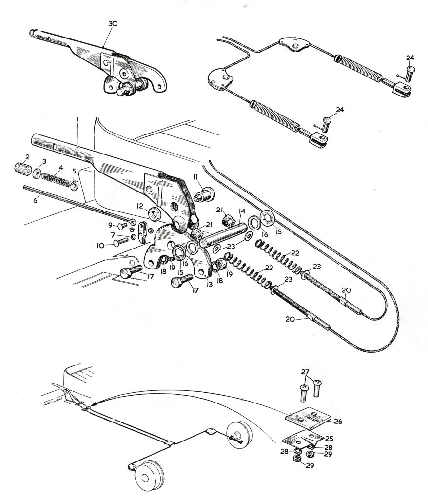
Exploded view of the Handbrake Mechanism
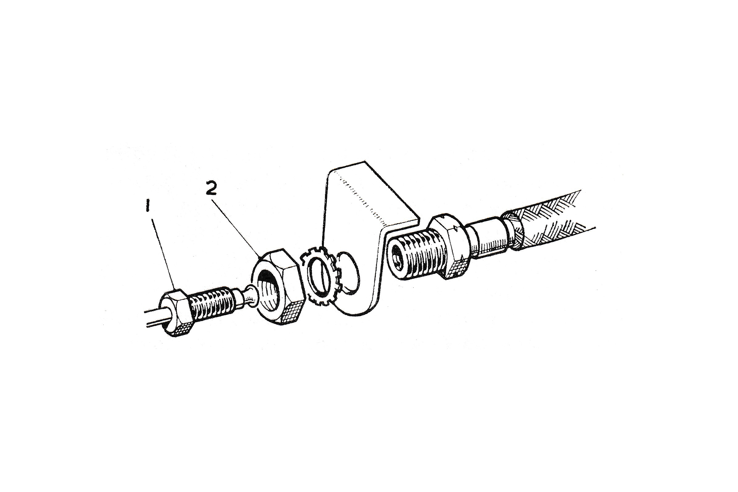
  1. Brake lever
  2. Release knob
  3. Felt anti-rattle washer
  4. Spring
  5. Plain washer
  6. Release rod
  7. Plain waher
  8. Pawl
  9. Rivet
  10. Pawl to pivot rivet
  11. Fulcrum pin
  12. Washer
  13. Ratchet
  14. Trunnion
  15. Trunnion washer
  16. Trunnion
  17. Lever to floor bolts
  18. Spring washers
  19. Nuts
  20. Hand brake cable
  21. Adjusting nut
  22. Adjusting spring
  23. Plain washer
  24. Clevis pin
  25. Hand brake cable fairlead
  26. Sealing pad
  27. Fairlead to floor screws (Philips)
  28. Spring washer
  29. Nut
  30. Handbrake lever assembly